The Build Process
- Jun 29, 2022
- 9 min read
Updated: Jul 25, 2023
*UPDATE* July 25, 2023
It's been awhile since I've had a chance to try and update this project and blog. Good news though, the Pi Looper now works with a Teensy 4.1! This makes the Pi Looper easier to build since the Teensy 3.6 is impossible to purchase. The newer version of this build uses an Adafruit NeoTrellis instead of the Sparkfun Button Pad 4x4 Breakout PCB. Now you can avoid drilling through the PCB to add the neopixels since they are built into the NeoTrellis.
I'm keeping the Teensy 3.6 build in the write up but I've added asterisks for the Teensy 4.1 updates. I did not test the Nintendo DS screen with the Teensy 4.1 build. The newer screens require different code and I don't know what needs to be changed. The 4x4 Breakout PCB wasn't tested with the Teensy 4.1 either. Everything should work if you want to use the original 3D printed case, otherwise, design a new one using the Adafruit NeoTrellis.
*UPDATE* December 28, 2022
I'm trying to figure out how to change the code to use an Adafruit 2.8" tft lcd with touchscreen instead of a separate screen and touchscreen. The eventual goal is to shrink this box down in size.
*UPDATE* September 26, 2022
It's been a few months since I last updated the site. I took some time to install Pure Data and the piLooper patch onto a Raspberry Pi 4 2gb and updated some of the steps to reflect installing the software onto the Pi 4. Some of these steps might work if you notice the same issues on the Pi 3.
-------------------
It took some time and a lot of pausing of the Pi Looper Guts YouTube video to successfully get the Pi Looper working! I'll continue to update this to try and clarify anything that doesn't make sense. This won't be a complete step by step guide. I'll be linking certain sites that helped me in the build, installing Pure Data on the Raspberry Pi and installing the firmware onto the Teensy. There are probably less complicated/better ways to do things and I am open to those suggestions to make this build easier.
I didn't document every step along the way so the pictures might jump around a bit on what is installed or soldered at the time. My soldering may not be pretty but it all worked in the end.
Make sure to visit Otem Rellik's GitHub for information, the Pure Data patch for the Raspberry Pi, code for the Teensy, the Thingiverse 3D files of the case and more.
I started this project back in January of 2022 so some of the software information I wrote is a little rusty.
Step 1:
Order all the parts:https://kuffcakes.wixsite.com/guide-to-build-otem/post/parts-list
Shop around for better prices if you want. Make sure you order logarithmic potentiometers and not linear ones for the loop volume controls.
The Raspberry Pi 3 B+ is difficult to find and the Teensy 3.6 is delayed until June 2023 according to the PJRC website:
*You can now substitute the Teensy 3.6 with a Teensy 4.1 and a Raspberry Pi 3 B+ with a Raspberry Pi 4.
Step 2:
*You'll now have to design your own case for this project if you use the Adafruit NeoTrellis.
Print or order all the parts for the Pi Looper. The files are located here:
Do not order the remix of Otem Rellik's case from the link. The remixed case is slightly thicker, which seems like a bonus but none of the parts will fit in their designated spaces. I had to shave down the slide pots spots, the button spots and where the Button pad PCBs go.
The hole for the 3d printed knobs are bigger than the logarithmic pots I linked in the parts blog. I already ordered all the parts and did not want to reorder more pots. You can try shopping for different pots*, modify the 3d models, fill the knobs with hot glue and push them in place, or order knobs that fit the pots. I opted for the 3rd option.
*If you find a logarithmic pot that the knobs fit, I'll change the item on the parts list.
You'll save money if you have a 3d printer or a friend with a 3d printer. I ordered all my parts from:


Step 3:
*You can skip this if you are using the Adafruit NeoTrellis.
You can start here or jump Step 9 to install the software and code onto the Raspberry Pi and Teensy. Wear eye protection and a face mask while drilling holes in the 4x4 and 2x2 Button Pads. Drill the holes to the size of the light and not the entire neopixel square like I did. I circled the button I screwed up when the drill stripped away a little of the button pad. The button was rendered useless and I had to re-drill a new 4x4 board.
Step 4:
Follow this guide on the Sparkfun website to solder the diodes onto the 4x4 Button Pad.

Step 5:
This one took awhile to figure out because there are not clear instructions on the Sparkfun website on using diodes on the 2x2 Button Pads. I combed through the discussion on the 2x2 Button Pad page and people wrote to use jumper wires instead of diodes. The buttons did not work for me using the diodes.

Step 6:
*Teensy 4.1 and NeoTrellis changes: the Clear button (T24) changes to T38 and the Play/Stop button (T25) changes to T39. The NeoTrellis SCL is T24 and SDA is T25.
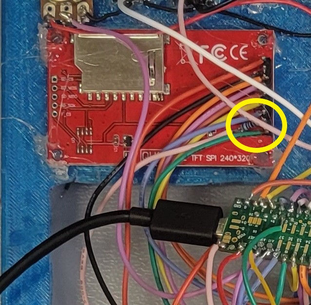
T is for Teensy and M is for Mux. Install all the buttons and potentiometers. Solder the grounds and power together. You should be able to link the ground and power to all the buttons and potentiometers. Do not put solder in the holes of the potentiometers.
Can you spot the break in the ground chain?

Insert the rotary encoder with the two pins on the left and three pins on the right.
Pin1 - T0
Pin2 - GND
Pin3 - T1
Pin4 - GND
Pin5 - T2

Right Board:
SWT-GND1 - T29
SWT-GND2 - T28
SWT-GND3 - T35
SWT-GND4 - T34
Left Board:
SWT-GND1 - T33
SWT-GND2 - T30
SWT-GND3 - T37
SWT-GND4 - T36
The SWITCH on both boards solder to a ground on the slide pots.

SWT-GND1 - T38
SWT-GND2 - T39
SWT-GND3 - T40
SWT-GND4 - T41
SWITCH1 - T45
SWITCH2 - T44
SWITCH3 - T43
SWITCH4 - T42
From Otem Rellik's GitHub
Teensy 3.6
Pin Description
0 Encoder Button
1 Encoder
2 Encoder
3 Mux control pin s0
4 Mux control pin s1
5 Mux control pin s2
6 Mux control pin s3
7 Input #1 Button
8 Input #2 Button
9 TFT - DC
10 TFT - CS
11 TFT - SDI(MOSI)
12 TFT - SDO(MISO)
13 TFT - SCK
14 Mux Control Sig pin
15 Main Volume Pot
16 Left Input Pot
17 Right Input Pot
18 Post Effects Reverb Pot
19 Post Effects Bitcruncher Pot
20 Post Effects Volume Slider
21 NintendoScreen yPin1
22 NintendoScreen xPin2
23 LEDs
24 Clear Button *For Teensy 4.1/NeoTrellis, this is now NeoTrellis SCL*
25 Play/Stop Button *For Teensy 4.1/NeoTrellis, this is now NeoTrellis SDA*
26 Instrument Select Button
27 Robo-drum Button
28 Loop 1 Button
29 Loop 2 Button
30 Loop 3 Button
31 NintendoScreen yPin2
32 NintendoScreen xPin1
33 Loop 4 Button
34 Loop 5 Button
35 Loop 6 Button
36 Loop 7 Button
37 Loop 8 Button
38 Drumpad Column *For Teensy 4.1/NeoTrellis, this is now the Clear button*
39 Drumpad Column *For Teensy 4.1/NeoTrellis, this is now the Play/Stop button*
40 Drumpad Column
41 Drumpad Column
42 Drumpad Row
43 Drumpad Row
44 Drumpad Row
45 Drumpad Row
Mux
Pin Description
0 Delay - Time Slider
1 Delay - Feedback Slider
2 Reverb Slider
3 Cutoff Slider
4 Ring Mod Slider
5 Bit Crusher Slider
6 Distortion Slider
7 Retrig Slider
8 Loop 1 Volume Pot
9 Loop 2 Volume Pot
10 Loop 3 Volume Pot
11 Loop 4 Volume Pot
12 Loop 5 Volume Pot
13 Loop 6 Volume Pot
14 Loop 7 Volume Pot
15 Loop 8 Volume Pot

Step 7:
*Teensy 4.1/NeoTrellis build, you won't need the 16 neopixels on the 4x4 board* Wire the neopixel lights together. The two that glow through the Pi eyes are not pictured. A little hot glue can be used to hold the neopixels down on the boards. Make sure the buttons are in place before using hot glue to tack the boards down. Do not solder the neopixels to the Teensy. Make sure the neopixels are oriented correctly. The 5v arrows should be going away from the Teensy (this made complete sense after the fact).


Step 8:
Use the pinouts on the board. It's a much easier soldering project... Solder the potentiometers to the MUX board. Solder the VCC pin to the power of a slide pot and GND pin to the ground of one of the slide pots.
Step 9: Take a break from soldering and install the software and code onto the Raspberry Pi and Teensy.
For the Teensy:
Follow the instructions on this page to download the Arduino software.
Open the program and open up the piLoopControl.ino file located on Otem Rellik's GitHub page.
There are a few libraries you need to install to make things work:
#include <Bounce.h> - library for the encoder and loop buttons
#include <font_Arial.h>
#include "SPI.h"
#include "ILI9341_t3.h" library for the the 2.2" screen
#include <Adafruit_NeoPixel.h> library for the neopixels
*For the Teensy 4.1/NeoTrellis build, #include <Adafruit_NeoTrellis.h> You will need to download the Adafruit seesaw library. Open Adafruit_NeoTrellis.h and search for Wire, which should be line 37 (in a row?). Change TwoWire *i2c_bus = &Wire); to TwoWire *i2c_bus = &Wire)2;. Pins 24 and 25 on the Teensy 4.1 are Wire2 for i2c. The NeoTrellis will not work unless this change is made or you modify the code.
Here is a link with the .ino file for the Teensy 4.1/NeoTrellis build.
Click on Tools and then go to Manage Libraries.
- Search for Bounce and install it.
Delete the 2 after Bounce if it shows up in the code. You want the older Bounce library.
- Search for SPI next and install the library labeled SD.
- Search for ili9341_t3 and download the library built by Paul Stroffregen
Click on Verify to make sure the code is ready to install. Hold off on installing the code so you can run a couple examples to test the 2.2" screen and the neopixels.
For the Raspberry Pi:
Download Raspberry Pi Imager.
Install Debian Bullseye onto the micro SD card.
For Pure Data:
Follow these instructions to install Pure Data on the Raspberry Pi.
These files are needed for Pure Data.
Unzip them into the Pd/Externals directory.
My files are located here:
/home/pi/Documents/Pd/externals
ggee-0.26 can also be installed by opening Pd, clicking Help, open Find Externals, and type in ggee.
*UPDATE*
I decided to try installing Pure Data and the piLooper patch onto a Raspberry Pi 4 2gb. I followed the instructions linked above to install Pd on the Pi 4. I installed ggee through Pd's Find Externals. I copied the comport files to the 'comport' directory but received an error when opening piLooper.pd. After a bit of research, I typed this into the Terminal and then everything worked:
sudo apt install pd-comport
The Teensy connected to the Pi after restarting the piLooper.pd patch.
Read the GitHub again regarding the drum samples. Start at line 1311 in the piLooper.pd code to see how to label your drum files. Place them in the directory where your patch is located. Example: my drum files are located in: /home/pi/Desktop/piLooper/
Go to line 4590 in the code to look at the directories. Change these directories to where your piLooper.pd patch is located. My patch is located here: /home/pi/Desktop/piLooper/

Step 10:
Back to soldering. Plan your wire layout in the case and cut the wires that will be used to wire the ILI9341 screen to the Teensy.
Follow this page to wire the 2.2" screen. The VCC and LED are wired on the same 3.3v pin.
I soldered the resistor to the LED pin instead of what is seen in the first picture since it is better protected.
The Arduino software has example code to install on the Teensy to test the screen.
Click on File, Examples and look for ILI9341_t3. I installed demosauce on the teensy. The program will start once the Teensy is powered on.

Step 11:
*I did not check the code linked in step 9 or go through it to see if the loop neopixels work.* Solder the neopixels to the Teensy. There is example code in the Arduino software to test the neopixels. Click File, Example and go to Adafruit Neo Pixel. Install strand test onto the Teensy and power it up. If the neopixels light up, it is time to upload piLoopControl.ino (or piLooper41.ino) onto the Teensy!

Step 12:
Upload piLoopControl.ino (or piLooper41.ino) onto the Teensy.
Solder everything onto the Teensy.
Connect the Nintendo DS screen to its board but don't secure the screen down yet. It needs to be tested for the correct orientation.

Step 13:
Plug the Teensy and the audio card into the Pi. Power the Pi up. The neopixel lights should start cycling through the rainbow. Enjoy the rainbow but don't taste the rainbow... Open Pure Data. Make sure the audio is being exported to the audio card.
Go to Pd
Click on Media
DSP On
Select ALSA
Select OSS-MIDI
Click on Audio Settings
Input Device: USB Audio CODEC (hardware)
Output Device: USB Audio CODEC (hardware)
*UPDATE*
I had to run through the next steps to remove an ALSA error on the Raspberry Pi 4:
type this into Terminal: cat /proc/asound/cards
Make a note of your USB-Audio number. Mine is 1.
Type this into Terminal: sudo nano /lib/modprobe.d/aliases.conf
look for: options snd-usb-audio index=-2 could be a different number)
Change the number to your USB-Audio number. Mine is: options snd-usb-audio index=-1.
Use Pure Data to open the piLooper.pd file. Some errors will pop up but then the piLooper screen will open. All the lights should look like this and the screen will turn on.
Step 14:
Next up is setting up the piLooper.pd patch to run when you start up your Pi.


Comments